Search
Filters
Close
RSS

Blog

PCI Express – What you really need to know!

PCI Express improves on PCI by using high speed multiple lanes. A single lane consists of a transmit and receive pair, which operate in full duplex at 500MB/s. The lanes can be grouped together in multiples to form links. For example a PCI Express x16 slot would have a single link made up of 16 lanes.

PCI Express connectors are available as x1, x4, x8 and x16 and offer the following bandwidths: -

LinksBandwidth
x1500MB/s
x4 2GB/s
x8 4GB/s
x16 8GB/s

Slots are not always what they seem

The PCI Express standard is very flexible. A plug-in card can be fitted to any slot which is at least as large as it is. For example a x1 card will function in a x1, x4, x8 and x16 slot.

Slots don’t have to be electrically wired with the full compliment of lanes, as long as the electrical power and ground connections are tracked in. It is common for products to have x8 or x16 physical slots which are only x4 and x8 respectively. For this reason, it is always necessary to read the fine print of the product specification.

A PCI Express card will negotiate and use what lanes are available on the socket it is plugged into. However, the function of a card could be severely impaired if it is running on less lanes that it was designed to make use of. This is an important consideration when using high performance peripherals such as RAID and graphics cards.

Graphics and Server Architectures

All motherboards and Single Board Computers (SBCs) are based around specific chipsets. Typically the chipset is made up of two large scale devices named the North and South bridge. These devices interface with the processor and all of the subsystems on the board.

Graphics based chipsets are optimised for multimedia use where high performance video is required and nearly all have a x16 link optimised for graphics card use. Some high end gaming motherboards have two or more x16 slots that support Nvidia ‘SLI technology’. In addition to the dedicated graphics link, four lanes are available to be configured as the board manufacturer wishes. Typically these will be utilised as four x1 board slots. Non-graphics cards should not be used in a x16 graphics slot unless the card manufacturer specifically states compatibility.

Server chipsets are designed to service high throughput plug-in cards such as RAID and fibre channel controllers. They do not have dedicated graphics links, so more lanes are available to be configured as the board manufacturer wants. This more flexible approach means that boards such as the Intel server motherboard S5000xxx are available in a number of variants with different PCI Express connector options. However, the maximum link size is usually limited to x8.

Single Board Computers and PCI Express - PICMG

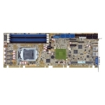
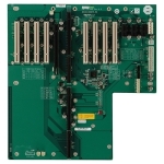
The international organisation which controls how Single Board Computers and backplanes are designed is called PICMG http://www.picmg.org/ . The latest version of the standard (PICMG 1.3) defines two separate classes of product which deal with graphics and server based architectures. The two standards are not interchangeable and it is possible to damage products if SBCs and backplanes from either class are mixed.

Most SBCs on the market are graphics class. This is due to the products being based on desktop processors and chipsets such as the Intel Core 2 Duo. Desktop chipsets also have more integrated features which make them a more cost effective option.

Server class SBCs are based on server chipsets and processors such as the Intel Xeon or an AMD Opteron processor.

Benefits of SSD vs. HDD

Introduction

Solid State Drive (SSD) technology has come on in leaps and bounds since it was first introduced during the 1980’s. Early models used volatile memory, such as DRAM which lost all data as soon as the power was lost and suffered from a very short working life.

With the advancement of SSD technology, including features such as wear levelling, error correction and TRIM SSD’s can achieve read/write speeds in excess of mechanical hard drives. Recent reductions in the price per Gb has also fuelled the popularity of SSD throughout modern computing platforms. Another contributing factor in the rise of SSD popularity can be attributed to the recent floods in Malaysia which are still affecting the availability and pricing of mechanical drives.

Write Speeds

With the ever increasing demand for data throughput over the years there has been a massive increase on data read/write speeds in both mechanical and solid state devices. On the performance side, the advantages of SSDs include faster boot time, faster random read / write and faster sequential reads for larger files. This has led to an improved user experience with less waiting time at start-up, loading applications, opening large files and in general use. Some SSD’s can accomplish read speeds up to 500MB/s (dependant on model, and manufacturer) and write speeds up to 300MB/s, this is continually increasing with the advancements made in technology. Some manufacturers are taking advantage of the now commonly used PCIe slots found in modern PC’s, with an increased bandwidth which pushes the read/write speeds even further.

Shock and Vibration

High resistance to shock and vibration, plus extended temperature ranges, makes SSD’s the ideal rugged replacement for applications where the mechanical hard drive will just not do.

Additionally, some manufacturers are able to offer MIL-STD drives that will suit the most demanding applications and requirements. From NSA approved deletion/destruction through to enhanced data security. With varying sizes in capacity, and physical dimension, 2.5” Standard drive through to Disk on Modules, there is an SSD to suit all applications and environmental requirements.

Components

The key components of Solid State Drives (SSD) are the controller and the memory used to store the data. The primary memory component in an SSD had been DRAM volatile memory since they were first developed, but since 2009 it is more commonly NAND flash non-volatile memory which had been introduced in 2002.

A key component of an SSD is the controller which incorporates the brains that bridge the NAND flash memory to the host computer, which performs the following functions:

  • Error Correction (ECC)
  • Wear Levelling
  • Bad Block Mapping
  • Read and Write Caching
  • Garbage Collection
  • Encryption

Heat, Noise and Power Consumption

In modern computers, the cooling fans and hard drives create levels of audible noise. Obviously, with no moving parts, SSD’s are completely silent giving them an additional advantage to embedded computers where noise levels are required to be minimal. Additionally SSDs consume far less power making them a greener option. Lower heat output also means system and cabinet cooling can be reduced; thereby further enhancing their green credentials.

Software for monitoring mechanical drives has been available for many years, and we are now seeing the emergence on to the market place for solid state drives to aid in the maintenance of the NAND flash, and ease the minds of the user in regards to the life cycle, and monitoring the life of the drive itself.

Operating Systems

Older versions of operating systems will continually write data back to the drive (page file), which will reduce the expected life duty of the NAND flash. Wear levelling has been advanced to help reduce the amount of cycles being used. Windows XP and Vista treat an SSD as a mechanical hard drive. To support the increasing market of SSD being used within systems, Microsoft added a number of features into Windows 7 to improve the life expectancy and performance of Solid State Disks:

  • Disk activity has been optimized to reduce the amount of disk writes and cache flushes. All SSDs have a limited number of write/erase cycles, so this reduction improves the life of the device as well as improving the speed of operation.
  • Disk defragmentation is disabled when a device is recognised as an SSD.
  • As data is written and erased from a standard hard drive over time it becomes fragmented . Defragmentation relocates data sequentially on the drive, so the head does not have to travel as much. This feature is not only unnecessary on an SSD, but the additional reading and writing of the process will shorten its life.
  • Windows 7 disables Superfetch, ReadyBoost and boot / application launch prefetching. These features were added to Windows Vista to improve the performance of conventional hard drive I/O but they have proved to be of no benefit for newer SSDs which make no distinction between random and sequential operation.
  • Windows 7 supports the ATA TRIM command. This feature gives the SSD the control to erase unused data blocks. This will reduce the number of block erase and merge operations to further extend the life of the SSD and improve performance.


What is PICMG 1.3?

PICMG 1.3 allows users to protect their investment in PCI (PCI-X) technology while taking advantage of the speed and increased bandwith of PCI Express.

What is PICMG 1.3?

  • Bringing PCI Express to your SBC increased speed and bandwidth

    Designed to interface with PCI Express peripherals on a backplane. The PCI Express interconnects with the backplane and can operate at x1, x4, x8, x16, and more depending on the capabilities of both the SHB and the backplane.

  • Support PCI (PCI-X) on board with flexibility

    The optional PCI (PCI-X) portion on the SHB interconnect with the backplane allows for 32-bit operation. The clock rate can be 33MHz, 66MHz, 100MHz, and 133MHz, depending on how the backplane and SHB are designed.

  • Miscellaneous I/O

    SATA, USB, IPMB, SMBUS, Geographic Addressing, and PCI Wake Up to the backplane is specified. Simplified the cabling on SHB for the system

PICMG 1.3 Key Features

  • PCI Express

    20 PCI Express lanes including x16, x4, and x1 PCI Express configuration are supported

  • Reset signal line defined

    Common header defined on backplane for reset function

  • ATX power signals are supported

    AUX voltages for stand-by power and sleep states (Soft starts, wake-on-LAN). Supports PSON#, PWRGD, PWRRBT#, and ACPI states.

Why PICMG 1.3?

  • This new technology is expected to allow PCIe transmission rates to keep pace with processor and I/O advances for the next 10 years or more.
  • Same basic mechanical dimensions are maintained to minimize chassis redesign expense.
  • Better host board power management and simplified I/O cabling
  • Supports PCI Express and PCI option cards without driver changing


Windows XP Professional for Embedded Systms

Windows XP Pro for Embedded Systems will continue to be available from IPCPRO through December 2016, and technical support will be offered through April 2014.

Windows XP Pro for Embedded Systems contains the same software bits and operates identically to Windows XP Pro. Windows XP Pro for Embedded Systems has licensing restrictions with restrict its use to and embedded solution. Windows XP Pro is used for general purpose PC’s. Windows XP Pro for Embedded Systems is used for embedded systems such as ATM’s, Kiosks, medical devices and industrial controllers.

The differences between an Enterprise Class HDD and Desktop Class HDD

Manufacturers stipulate testing methodologies for both enterprise class hard drives and desktop class hard drives. They state the enterprise drives are tested using enterprise conditions and must operate in 24 x 7 environments, and the desktop drives are tested using a typical 40-hour work week conditions. We wish to share some of the salient technical features that effect both drives and why careful attention needs to given to these attributes.

Error Recovery Time limits

Modern hard drives feature an ability to recover from some read/write errors by internally remapping sectors and other forms of self test and recovery. The process for this can sometimes take several seconds or (under heavy usage) minutes, during which time the drive is unresponsive. RAID controllers are designed to recognize a drive which does not respond within a few seconds, and mark it as unreliable, indicating that it should be withdrawn from use and the array rebuilt from parity data. This is a long process, degrades performance, and if a second drive should fail under the resulting additional workload, it can be catastrophic.

Enterprise drives have this value set at around ~ 7-8 seconds, after which time if the disk is has not recovered from the error it issues an error message to the RAID controller and defers the error recovery until a later time. This will let the RAID controller decide on how to handle the recovery issue.

By contrast the Standard (Desktop) Drives have this feature turned off as it is assumed that there is no RAID card. During its recovery process the disk becomes non-responsive and it will not issue any type of error message. At this point he RAID controller will issue instructions to mark the drive as bad and proceeds to remove it from the RAID array. Desktop drive firmware is designed with the assumption that there is no RAID controller present and for the drive to do everything possible to complete the error correction cycle.

Rotational Vibration Tolerance

One of the greatest hindrances to hard disk performance and reliability is vibration. Much like a needled on a record, the disk drives head must try to follow narrow data tracks in order to read (or write) information. Physical disturbances can throw the head off-track and cause a delay while the actuator repositions it. This eventually has an impact on the hard drive’s input/output Performance.

In modern, balanced hard drives, linear back-and-forth vibration barely affects the operation of the drive head. However, circular movements—rotational vibration—can cause serious disruption. These problems are particularly acute in multi-drive systems (NAS, DAS), because drives tend to be installed alongside each other in arrays. The vibration caused by the rotation and seek activities of nearby drives can affect the whole array, progressively disturbing the operation of each drive in the system.

The main sources of Rotational Vibration (RV) energy are: 1) the drive’s self-actuation, 2) additional drives inside the cabinet accessing data, and, 3) external forces acting on the cabinet. If RV is not taken into account in the design of the drive, the force of RV can push the head off track causing missed revolutions and delays in data transfers. Tests on drives not capable of handling RV have shown significant reductions (over 50%) in performance.

Most enterprise class RAID drives combat vibration-induced performance degradation with sensors that allow the drives to tolerate a larger rotational vibration window. These sensors allow the drives to compensate for the rotational vibrations by using a closed feedback loop between the head and the spindle. It can sense vibration anomalies and adjust the drive head accordingly.

Enterprise class drives usually have more servo wedges in the disks tracks then compared to desktop drives. These wedges are used to determine the location of the head in relation to the track. If a head misalignment is detected it will suspend the read or write and wait for the target location to come under the head again. Enterprise drives use dedicated servo and data path processors along with servo algorithms in the drives firmware to help with this compensation.

Desktop class drives on the other hand are designed not to have to deal with so many vibrations issues, and as such this means they don’t have sophisticated mechanisms to compensate for vibration induced errors. Desktop class drives usually have less servo wedges and only one combined servo and data path processor with no firmware compensation algorithms. This means they are more susceptible to rotational vibration errors.

Without these vibration sensors, extra servo wedges, dedicated servo and data path processors, and compensation algorithms, you will likely see symptoms of vibration related errors including lower drive performance, a larger number of medium errors, and an increased frequency of drives marked offline by the RAID controller.

Error Correction – Data Integrity

One feature of an enterprise-class system is the implementation of “end-to-end” error detection. Enterprise class drives use ECC for data passing through drive memory and may use additional error detection methods for data transmitted within the drive electronics. Data that is transmitted from one end of the drive to the other with this system would be accompanied by some type of parity or checksum at every stage. This will allow for data transmission errors to be detected, and in some cases corrected or retransmitted. The form of this error detection and correction capability is usually proprietary to the drive vendor.

Desktop class drives deployed within subsystems do have error detection, but do not usually support end-to-end data protection that the Enterprise class drives implement. The reason for this is the lack of Error Correction Code (ECC) within the system memory or drive memory buffers.

Quality Differences

More often than not manufacturers may discuss the quality of the parts used in the manufacturing of both class of drives, manufactures may differentiate enterprise from desktop drives by not testing certain enterprise-class features, validate drives with different test criteria, or even disable enterprise features in desktop class drives to ensure differentials for pricing and marketing purposes. Aside from the main differences already outlined, we have not been able to distinguish the differences on a component level despite having physically dismantled both class drives and extensively compared the two, aside from the firmware differences. All other variances are a subject of this report. The only product that bucks this trend is the Seagate Constellation SATA drives that are designed form the ground up and use components that are not comparable to any of the desktop class drives we looked at (all 2TB drives).

As hard drive technologies keep evolving; customers continue to have a choice of products to use for their storage requirements. It is important to balance the critical nature of your data with hard drive features and system requirements to ensure these adequately meet with your specific needs to store, protect and share your data. Selecting the correct drive class will enable the critical areas of qualities, functionally, performance, and most of all reliability to be optimized for the targeted implementation.